










Product Details
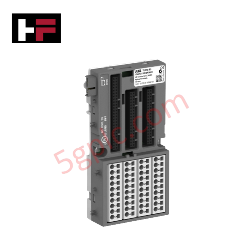
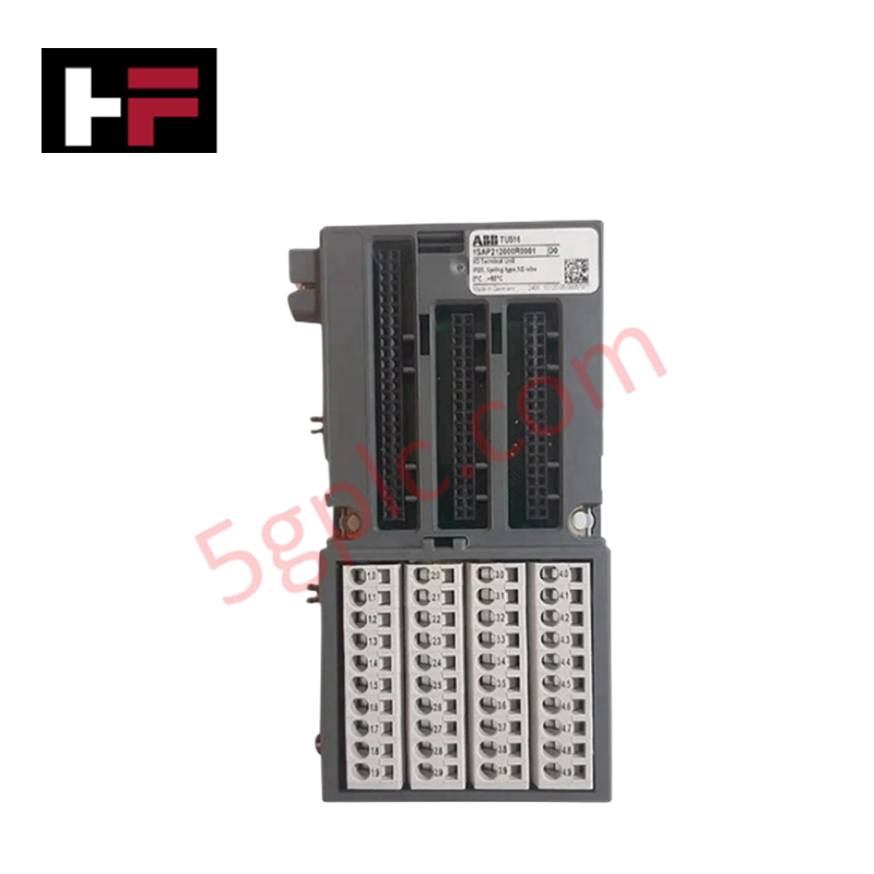
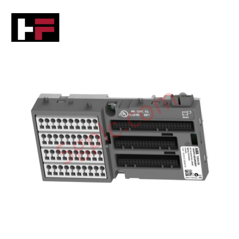
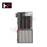
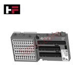
Configured for field I/O bus interface mounting and signal routing in S500 I/O platforms, the ABB TU551-CS31 1SAP210600R0001 (TU551-CS31 Interface Terminal Units) provides direct physical/electrical execution.
Hardware Specifications
| Parameter | Specification |
|---|---|
| Model | TU551-CS31 |
| Part Number | 1SAP210600R0001 |
| Brand | ABB |
| Product Type | Interface Terminal Units |
| Origin | Germany |
| Weight | 0.236 kg |
| Dimensions | 67.5 x 135 x 28 mm |
| Operating Temp | 0 to +60 deg C |
| Power Consumption | 24 VDC supply voltage |
| Terminal Type | Screw terminals |
| Fieldbus Protocol | CS31 protocol |
| Ingress Protection | IP20 |
Backplane Bus Communication Velocity and Network Determinism
The interface terminal unit links remote S500 I/O modules directly to the CS31 fieldbus network, maintaining steady backplane bus communication velocity across adjacent terminal slots. Integrated signal paths preserve transmission speed and firmware flash compatibility between connected bus modules and the primary controller. Screw terminal blocks maintain secure galvanic contact, minimizing contact resistance and preventing cross-talk across high-density I/O distributions.
Frequently Asked Questions
Q: Does the TU551-CS31 unit contain active processor components?
A: No, the TU551-CS31 functions as a passive mounting and wiring base that routes power, field signals, and bus communication to the plugged-in S500 I/O interface module.
Q: How is physical chassis earth grounding completed for the terminal base?
A: Frame grounding is established automatically through the integrated metallic rear grounding contact clips when snapped onto a grounded DIN rail.
Q: Can terminal wiring be modified while the system is powered?
A: Field supply voltage must be turned off prior to attaching or disconnecting field wires on the screw terminals to avoid electrical shorts.
Field Installation Guidelines
- Turn off primary 24 VDC power sources prior to mounting or wiring the TU551-CS31 unit.
- Snap the 67.5 x 135 x 28 mm terminal base onto a standard 35 mm DIN rail until the locking spring engages.
- Verify mechanical continuity between the rear metal grounding clips and the grounded DIN rail.
- Strip field wiring ends to specified lengths and secure them tightly into the screw terminal blocks.
- Maintain a minimum clearance of 200 mm between CS31 fieldbus cabling and high-voltage AC conductors to reduce electrical noise.
Additional Information
- 100% Genuine Parts: All products are original and authentic, ensuring reliable industrial performance.
- 30-Day Refund Guarantee: Return any in-stock item within 30 days in original, unopened packaging for a full refund (excluding shipping and fees).
- 12-Month Warranty: Covers defects in materials or workmanship; excludes misuse, normal wear, or unauthorized modifications.
- Worldwide Shipping: We ship via USPS, UPS, FedEx, and DHL. Delivery times vary by country and may be subject to customs or import fees.
- Support & Contact: Technical and warranty assistance is available anytime. Contact us here: Contact.
- Purchase Guidance: Check product specifications and compatibility carefully before ordering to ensure proper application.









Tech & Buying Guide

Spatial Computing in Industrial Automation: Elevating PLC and DCS Operations with AR and VR
Industry 4.0 integrates digital intelligence into field operations, transforming factory automation landscapes worldwide. Spatial technologies—specifically Augmented Reality (AR) and Virtual Reality (VR)—redefine how engineers interact with industrial control systems. By bridging computer-generated CAD models with real-time operational technology (OT) data, immersive displays enable intuitive monitoring, rapid diagnostics, and safer maintenance across complex processing facilities.

Master Acceptance Testing: Understanding FAT and SAT in Industrial Control Systems
Factory Acceptance Testing (FAT) and Site Acceptance Testing (SAT) serve as critical quality assurance gateways in complex industrial control systems. Both procedures verify that programmable logic controllers (PLCs), distributed control systems (DCS), and associated field devices meet strict functional specifications. However, executing these tests effectively requires clear delineation between off-site staging and final field commissioning.

Industrial Networking Essentials: Demystifying Hubs, Switches, and Routers in Control Systems
Industrial automation relies heavily on robust networking infrastructure to connect programmable logic controllers (PLCs), distributed control systems (DCS), and human-machine interfaces (HMIs). Modern factory automation environments generate vast amounts of real-time operational data across deterministic networks. Understanding the structural differences between hubs, switches, and routers ensures optimal traffic segmentation, minimizes latency, and maintains high network availability.