










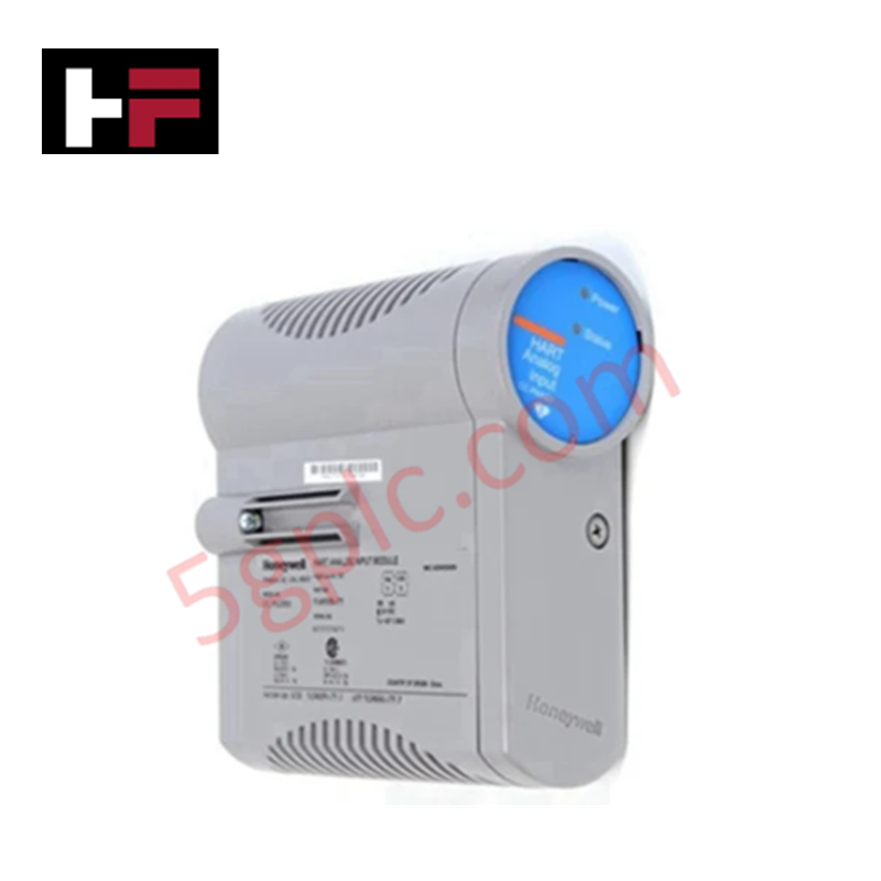

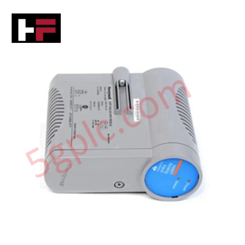

Product Details
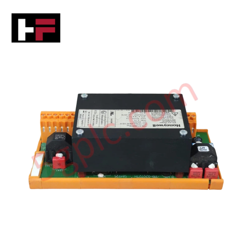
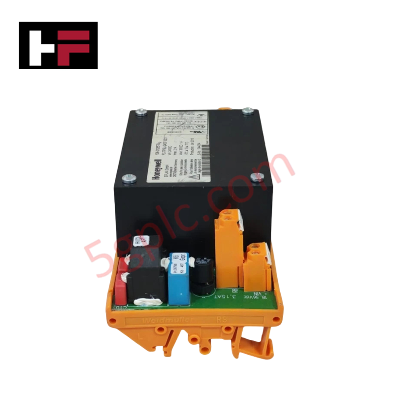
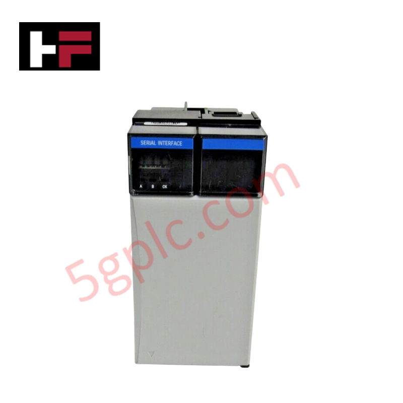
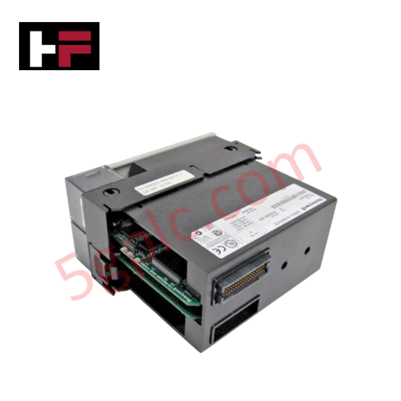
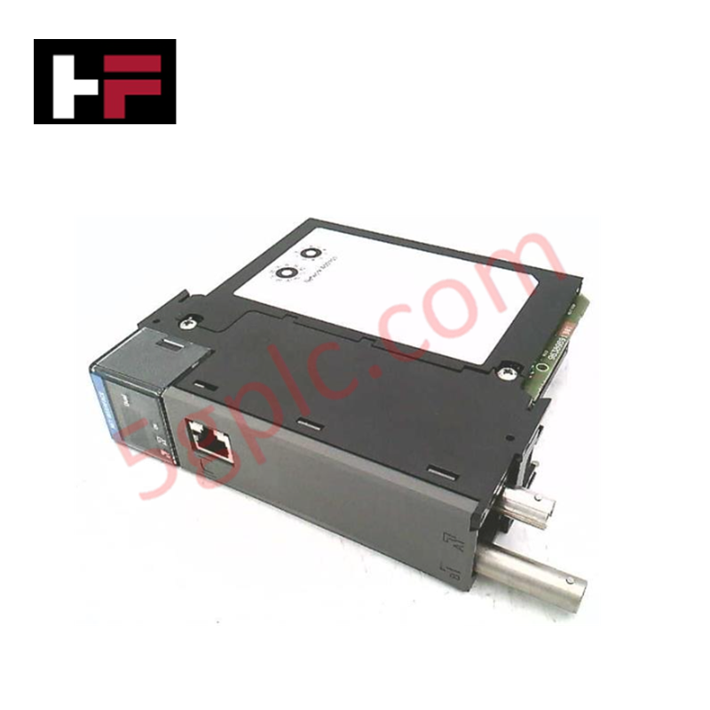
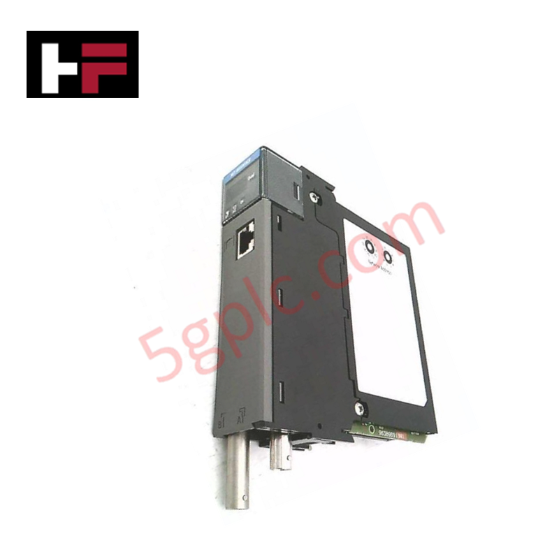
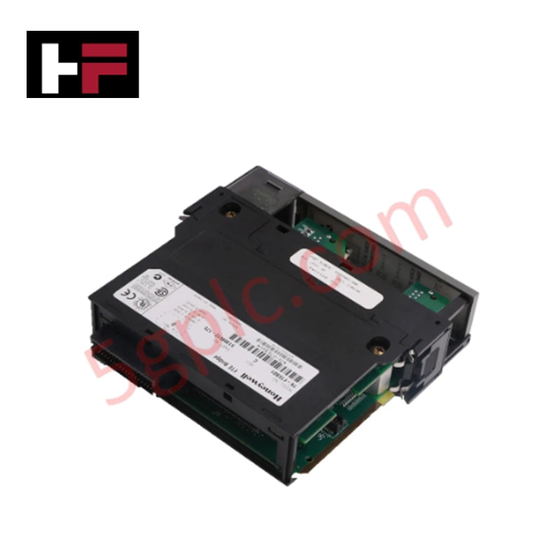
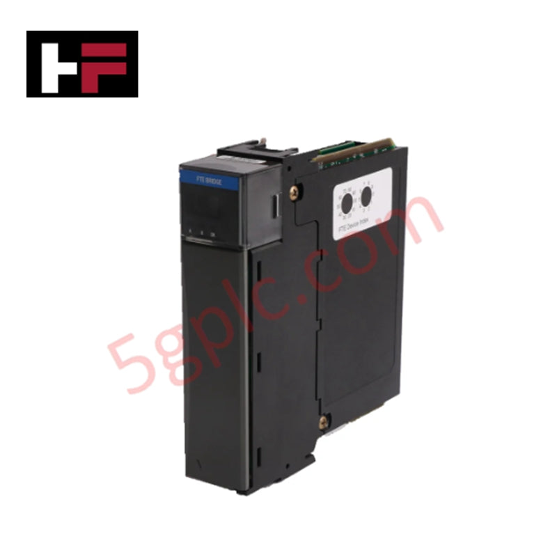
The Honeywell 8U-PWSP01-CN, also cataloged as the 8U-PWSP01-CN Power Supply Module, operates as a dedicated hardware component for regulated system bus voltage delivery within Honeywell Experion PKS Series 8 platforms.
Hardware Specifications
| Parameter | Specification |
|---|---|
| Model | 8U-PWSP01-CN |
| Brand | Honeywell |
| Origin | USA |
| Weight | 0.4 kg |
| Dimensions | 7 cm x 14 cm x 14.5 cm |
| Operating Temp | -25 deg C to +70 deg C |
| Power Consumption | 100-240 VAC / VDC input |
| Output Voltage | 24 VDC |
| Output Current | 20 A |
| Voltage Regulation | +/-0.5% |
| Isolation | 2000 VAC |
| Redundancy | Supported |
| Thermal Monitoring | Six internal temperature sensors |
Galvanic Isolation & Voltage Regulation Profiles
The module converts wide-range AC or DC input power into a tightly regulated 24 VDC power rail delivering up to 20 A to backplane I/O channels. Internal galvanic isolation rated at 2000 VAC prevents line transients and noise from coupling onto the internal DC distribution bus. Integrated circuitry maintains output regulation within +/-0.5% across dynamic load steps. Six internal thermal sensors continuously monitor operating states, providing contact signaling and status indication to protect against over-temperature events.
Frequently Asked Questions
Q: Does the 8U-PWSP01-CN support redundant power configurations on the Series 8 rack carrier?
A: Yes, the module supports redundant parallel operation to allow uninterrupted 24 VDC system power delivery during a single supply failure.
Q: What input power sources are compatible with the primary terminals?
A: The internal switching power circuit accepts an input range of 100-240 VAC or VDC.
Q: What isolation level exists between input power and system ground?
A: The hardware architecture provides 2000 VAC galvanic isolation between input power terminals and the internal control logic circuits.
Field Installation Guidelines
- Ensure the AC/DC main line circuit breaker is de-energized prior to seating or unseating the 8U-PWSP01-CN power module in the Series 8 rack slot.
- Verify that input line, neutral/DC potential, and protective earth (PE) wires are fully secured to terminal connections before applying power.
- Establish a direct low-impedance ground connection from the rack chassis grounding stud to the main enclosure ground bar.
- Maintain proper vertical clearance above and below the module chassis to allow natural air circulation across the heat sink surfaces.
- Confirm that total continuous 24 VDC load currents do not exceed the 20 A maximum rating under peak ambient operating conditions up to +70 deg C.
Additional Information
- 100% Genuine Parts: All products are original and authentic, ensuring reliable industrial performance.
- 30-Day Refund Guarantee: Return any in-stock item within 30 days in original, unopened packaging for a full refund (excluding shipping and fees).
- 12-Month Warranty: Covers defects in materials or workmanship; excludes misuse, normal wear, or unauthorized modifications.
- Worldwide Shipping: We ship via USPS, UPS, FedEx, and DHL. Delivery times vary by country and may be subject to customs or import fees.
- Support & Contact: Technical and warranty assistance is available anytime. Contact us here: Contact.
- Purchase Guidance: Check product specifications and compatibility carefully before ordering to ensure proper application.


Tech & Buying Guide

Understanding Root Causes of Unplanned PLC Stop Mode in Industrial Automation
Modern Programmable Logic Controllers manage execution through distinct operational states: Run, Stop, Start-Up, and Hold. During power-up, a controller initializes memory registers within Stop mode before briefly transitioning to Start-Up mode. During this phase, internal self-diagnostics evaluate system integrity across hardware and user programs. If the controller detects no critical faults, it enters Run mode to execute the control program continuously. However, any severe system anomaly forces the CPU back into Stop mode immediately to prevent erratic machine behavior across the plant floor.

Human-Machine Interface Design: Essential Guide to HMI Selection, Visualization, and Control System Integration
Human-Machine Interfaces (HMIs) serve as the primary operational window into complex industrial automation systems. Modern HMIs convert raw machine data into clear graphical displays, enabling operators to oversee entire manufacturing processes in real time. Instead of relying on physical control panels full of hardwired switches, engineers program interactive screens using intuitive graphics, dynamic color coding, and responsive touch interfaces. Over my 15 years in control systems engineering, I have observed HMIs transform from basic display screens into sophisticated command centers that drive operational efficiency across DCS and PLC environments.

Understanding Safety Relays in Industrial Automation: Architecture, Operation, and Functional Safety
Standard electromechanical relays provide basic electrical isolation between low-voltage control circuits and high-power output loads. A traditional switching relay features a magnetic coil driving mechanical Common (COM), Normally-Open (NO), and Normally-Closed (NC) contacts. However, standard relays pose severe functional risks when deployed in critical safety interlock circuits. High current inrush or mechanical wear can weld contacts together permanently. If contact welding occurs in an emergency stop circuit, pressing the button fails to halt hazardous machinery movements. Consequently, global functional safety standards prohibit standard relays for critical machine guarding functions.